Ready to make your home cozier? Well, Our complete guide to wiring Honeywell thermostats is here to make things easy. No more confusion; just straightforward instructions for installation or replacement. Whether you’re dealing with a single-stage setup or a more complex multi-stage system, we’ve got all the details covered.
But before we dive into the wiring tutorials, let’s take a quick look at the Honeywell thermostat wiring code. This will help you get familiar with the wire colors and their functions.
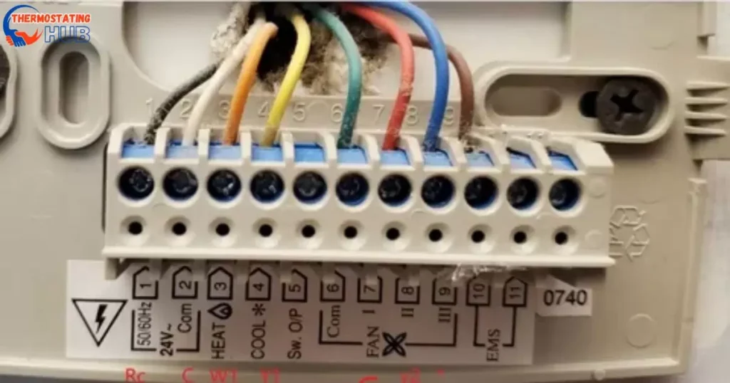
Honeywell thermostat wiring color code
| Wire Color | Terminal | Function |
| Red | R/Rh/Rc | Power (24VAC) |
| Blue | C | Common (24VAC) |
| White | W/W1 | Heat relay (Stage 1) |
| Brown | W2 | Heat relay (Stage 2) |
| Green | G | Fan relay |
| Yellow | Y/Y1 | Compressor contactor (Stage 1) |
| Light blue/ others | Y2 | Compressor contactor (Stage 2) |
| Orange | O/O/B | Reversing valve (Cooling/Heat pump) |
| Brown | E/Aux/W2 | Emergency heat |
| Not fixed | L/A | Heat Pump fault input |
| Not fixed | K | Honeywell saver module |
| Not fixed | S | Outdoor temperature sensor |
| Not fixed | U | Unused |
Now, you’re all set to wire your Honeywell thermostat like a pro! If you ever get stuck, just refer back to this guide for easy reference. Happy wiring!
Preparing your thermostat for wiring
Getting your thermostat ready for wiring? Follow these simple steps:
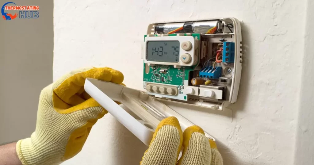
- Power Off: First things first, turn off the power to your heating and cooling system. Switch off the circuit breaker that controls your HVAC system to avoid any electrical mishaps during the wiring.
- Remove Old Thermostat: Carefully remove the old thermostat from the wall. Note which wires are connected to each terminal and their labels.
- Snap a Photo: Before touching any wires, snap a clear photo of the wiring setup. It’ll be your handy reference when installing the new Nest thermostat.
- Label the wires: If you’re swapping out an old thermostat, label each wire according to its terminal. This makes sure you match them correctly to the new thermostat’s terminals.
- Secure Wires: Stop the wires from slipping back into the wall. Use tape to hold them in place temporarily, or gently thread them through a pen or pencil to keep them secure.
- Install Nest Base: Fix the Nest thermostat base on the wall with the provided screws and a screwdriver. Ensure it’s firmly in place and level.
- Prepare wires: If necessary, strip about ⅓ inches from the wire ends for a proper connection. Remove excess insulation, keeping the wire strands neat and undamaged.
Now, you’re set to wire up your Nest thermostat hassle-free! Need a quick reminder? Just refer back to these steps. Happy wiring!
Things you need to be aware of before replacing your old thermostat with a new Honeywell
If your system is all about heating and nothing else, make sure to grab a thermostat that’s got your back. Some thermostats are exclusively designed for heat pump systems, so keep an eye out for those too.
Let’s break it down: If your thermostat has only 3 wires, chances are it’s tailored for a specific purpose. Typically, thermostats made just for heat pumps might skip the W terminal, which is all about controlling the heat.
So, before you make the purchase, double-check that your thermostat matches your system like a perfect puzzle piece. No W terminal? No problem! Just find the right thermostat buddy for your heat-only setup.
Honeywell 1st Stage Heat Pump System with 1 Compressor (6 Wire)
Here’s a breakdown for wiring your thermostat based on your heat pump system:
| Wire | Function |
| R | Power |
| Rc | R+Rc joined by Jumper/Slider |
| Y | Compressor contactor |
| C | 24VAC common |
| O/B | Changeover valve |
| G | Fan relay |
| W | Not needed in heat pump system |
For a first-stage heat pump system with six wires, you’ve got the fan relay for controlling the fan and the O/B reverse valve that switches between the heat and cool modes.
Now, if you’re rolling with a single-stage heat pump system and rocking just 1 Y wire for the compressor relay, you’re all set.
But let’s talk about R wires. If you’ve got separate R wires (R and Rc), connect both to their respective thermostat terminals. No separation? No problem! Connect that lone R wire to one terminal and pop a jumper between them.
For Honeywell Pro Series thermostats, if you’ve got only one R wire and it’s cozying up to R, Rc, or RH, slide that tap up (1 wire). But if there’s one wire on R and one on Rc, slide it down (2 wires).
Wiring made easy, just like a heat pump should be!
Honeywell 1st Stage Heat Pump With Auxiliary/ Emergency Heat (7 wire)
For 7-wire Honeywell thermostat wiring, especially in a first-stage heat pump system, here’s the lowdown:
| Wire | Function |
| R | Power |
| Rc | R+Rc joined by slider tab. |
| Y | Compressor contactor |
| C | 24VAC common |
| O/B | Changeover valve |
| G | Fan relay |
| Aux/E | Auxiliary heat/Emergency heat relay |
| L | Heat pump fault input (Controls indicator lights) |
| W | Do not use this terminal for heat pump applications! |
So, in the mix of wires, the Y wire takes the lead, controlling the first-stage compressor relay. Then, there’s the Aux/E wire. Aux kicks in automatically during extreme weather when your heat pump needs a little extra help. E, on the other hand, is like a manual switch for extra heat.
And if you spot an L terminal, that’s your heat pump fault input wire. It’s the maestro behind those indicator lights on your thermostat. So, when the system leans on auxiliary or emergency heat or when there’s a hiccup, those indicator lights dance, all thanks to the L wire.
Keep your thermostat wiring symphony in harmony!
2 Stage Heat Pump System With Two Compressors (8 Wire)
In a two-stage heat pump system without secondary heating, like a furnace or auxiliary heating, things get a bit dynamic. Here’s the breakdown for your thermostat wiring:
| Wire | Function |
| R | Power |
| Rc | R+Rc joined by slider tab. |
| Y | Compressor contactor (stage 1) |
| C | 24VAC common |
| O/B | Changeover valve |
| G | Fan relay |
| Y2 | Compressor contactor (stage 2) |
| L | Heat pump fault input |
| W | Do not use this terminal for heat pump applications! |
Now, with a two-stage setup, you’ve got two Y wires stealing the spotlight. The first Y wire takes charge of the compressor contactor for stage 1, and the second Y2 wire steps in for the compressor contactor in stage 2. It’s like a tag team, ensuring your heat pump works seamlessly.
But remember, there is no need to use the W terminal in this scenario for heat pump applications. Keep it simple, keep it wired right! 🔄
Read Also: Can You Use Nest Thermostat Blue Wire as C Wire?
2 Stage heat pump system with Auxiliary heat/ Emergency Heat Pump System (10 Wire)
For a sophisticated heat pump boasting 2-stage heating with dual compressors and a sidekick of secondary heating, the wiring game gets a bit more intricate.
Here’s the cheat sheet for your thermostat wiring:
| Wire | Function |
| R | Power |
| Rc | R+Rc joined by slider tab. |
| Y | Compressor contactor (stage 1) |
| C | 24VAC common |
| O/B | Changeover valve |
| G | Fan relay |
| Aux/E | Auxiliary heat/heat relay |
| Y2 | Compressor contactor (stage 2) |
| L | Heat pump fault input |
| W | Do not use this terminal for heat pump applications! |
Here’s the magic: Y1 takes charge of the compressor relay for stage 1, Y2 swoops in for the compressor relay in stage 2, and the Aux/E wire is the maestro orchestrating the dance of secondary heat. It ensures your heat pump is ready for any temperature twist.
Remember, steer clear of the W terminal for this heat pump masterpiece. Wiring perfection achieved! 🔥
Dual Fuel System (TH6320U / TH6220U only)
Let’s simplify the wiring game for your heat pump. Here’s a quick guide:
| Wire | Function |
| R | Power |
| Rc | R+Rc joined by slider tab. |
| Y | Compressor contactor (stage 1) |
| C | 24VAC common |
| O/B | Changeover valve |
| G | Fan relay |
| Aux | Auxiliary heat |
| E | Emergency heat relay |
| Y2 | Compressor contactor (stage 2 – if needed) |
| L | Heat pump fault input |
| S | Outdoor sensor |
| W | Do not use this terminal for heat pump applications! |
Keep it straightforward: R for power, Y for stage 1 compressor, and if you’re up for stage 2, Y2’s got your back. The Aux wire ensures your auxiliary heat is ready for action, and E is the emergency heat switch. Add in the outdoor sensor with the S wire for a weather-smart setup. Just avoid the W terminal for your heat pump application. Ready to wire up? 🚀
Honeywell Thermostat Wiring For Conventional Systems (forced air and Hydronics)
For a conventional heat and air conditioner with a single transformer using a 6-wire setup, your thermostat wiring is as straightforward as it gets.
Here’s the breakdown:
| Wire | Function |
| R | Power |
| Rc | R+Rc is joined by slider tab. |
| Y | Compressor contactor |
| C | 24VAC common |
| W | Heat relay |
| G | Fan relay |
No fuss, just the essentials. R powers it up, Y handles the air conditioner compressor, W is your primary heat relay, and G takes care of the fan relay. Keep it simple; keep it wired right!
Heat-only System ( 3 Wire)
For a radiant heating system, simplicity is key with just three wires. Here’s the breakdown:
| Wire | Function |
| R | Power |
| C | 24VAC common |
| W | Heat relay |
Power up with R, keep things common with C, and let W handle the radiant heat relay. Straightforward and effective for a cozy setup!
Radiant Heat-only System: Series 20 (4 wire)
Don’t forget to tweak your settings for radiant heat. Here’s the quick guide for your wiring:
| Wire | Function |
| R | Series 20 valve terminal “R” |
| Y | Series 20 valve terminal “W” |
| C | 24VAC common |
| W | Series 20 valve terminal “B” |
Ensure your system is set to radiant heat and let the wires do their job. R, Y, C, and W – a simple combination for a warm and cozy space! 🌡️
Honeywell Radiant Heat-only System: Power open zone valve (3 wire)
For a Honeywell Pro Series thermostat in a setup where cooling power (Rc) isn’t needed, follow these simple steps:
| Wire | Function |
| R | Power |
| W | Valve |
| C | 24VAC common |
Keep it streamlined – R for power, W for the valve, and C for common. If you’re rocking the Honeywell Pro Series, slide that tab to the top position for the “R” setting. Easy peasy! 🔧
Furnace with 1st Stage Air Conditioner (5 wire)
For a heating system with a simple 5-wire setup, here’s the breakdown:
| Wire | Function |
| R | Power (heating transformer) |
| Y | Compressor contactor |
| C | 24VAC common |
| W | Heat relay |
| G | Fan relay |
Power up with R, let Y handle the compressor contactor, C keeps things common, W takes care of the heat relay, and G gets the fan relay running. All set for toasty warmth! 🔥
Heat-only System with Fan (4 wire)
For a heat-only system or a furnace with a fan, a neat 4-wire setup covers the essentials:
| Wire | Function |
| R | Power |
| C | 24VAC common |
| W | Heat relay |
| G | Fan relay |
Power up with R, keep it common with C, let W handle the heat relay, and G gets the fan relay going. Simple and effective for your heating needs!
Honeywell Cool-only System: Air Conditioner (5 wire)
Wiring your air conditioner is a breeze! Just follow these simple steps:
| Wire | Function |
| R | Power |
| Rc | R+Rc joined by Slider Tab |
| Y | Compressor contactor |
| C | 24VAC common |
| G | Fan relay |
Get powered up with the red wire in the R terminal, join Rc if needed, let Y handle the compressor, C keeps it common, and G gets the fan rolling. Easy connections for a cool and comfy space!
2-stage furnace with 2-stage air conditioner (1 transformer)
To wire a Honeywell thermostat for an air conditioner, follow these straightforward steps:
Connect the wires for power and cooling control:
- The red wire (R) goes to the R terminal for power.
- The yellow wire (Y) connects to the Y terminal for cooling control.
- Green wire (G) links to the G terminal for fan operation.
- Blue wire (C) finds its place in the C terminal for a common connection.
For heating, follow these additional steps:
- White wire (W) hooks up to the W terminal for the first stage of heating.
- The second white wire (W2) goes to the W2 terminal for the second stage of heating.
- The second yellow wire (Y2) connects to the Y2 terminal for the second stage of cooling.
Remember, always refer to the specific thermostat’s manual for accurate wiring instructions. Here’s the breakdown in a chart:
| Wire | Function |
| R | Power |
| Rc | R+Rc joined by slider tab. |
| Y | Compressor contactor (stage 1) |
| C | Common |
| W | Relay (stage 1) |
| G | Relay |
| W2 | Heat relay (stage 2) |
| Y2 | Compressor contactor (stage 2) |
Follow these guidelines, and your thermostat will be all set for a comfortable living space!
What is the K wire on a Honeywell thermostat?
Certainly! If you have a system that doesn’t provide the C wire but your thermostat needs one, you can use the Honeywell module saver, often labeled “K.” Here’s how to connect them:
The K wire, which is a combination of the Y and G wires, should be connected to the C terminal on thermostats that require the C wire.
This module saver, the Honeywell K, acts as a workaround, providing the necessary common connection for your thermostat and ensuring everything runs smoothly.
Key Takeaways for Honeywell Thermostat Wiring in Heat Pumps
Here are the key takeaways for Honeywell thermostat wiring in heat pumps:
Wiring Essentials:
- Red (R) wire for power.
- Yellow (Y) wire for the compressor contactor.
- Green (G) wire for the fan relay.
- Blue (C) wire for a common connection.
- White (W) wire for the first stage of heating.
- Second white wire (W2) for the second stage of heating.
- Second yellow wire (Y2) for the second stage of cooling.
Additional Modules:
- The Honeywell module saver (K) combines Y and G wires and connects to the C terminal if your thermostat requires a C wire.
Thermostat Preparation:
- Turn off the power before wiring.
- Remove the old thermostat carefully, noting wire connections.
- Take a photo for reference before disconnecting wires.
System-Specific Wiring:
- Radiant heating systems may only need R, C, and W wires.
- For air conditioners, R, Y, C, and G wires are typically used.
Thermostat Setting:
- For Honeywell Pro Series thermostats, adjust the slider tap based on the number of R wires.
Reference Guide:
- Consult the specific thermostat’s manual for accurate wiring instructions.
- Use this guide as a reference for future installations or clarifications.
Troubleshooting:
- If you encounter issues or have model-specific questions, leave a comment or contact us through the email provided on the website.
By following these takeaways, you’re well-equipped to handle the wiring of your Honeywell thermostat for optimal comfort control in your home.
Pros and Cons of Honeywell Thermostat Wiring for Heat Pumps
Pros of Honeywell Thermostat Wiring for Heat Pumps:
- Comprehensive Guide: The provided guide offers a detailed, step-by-step approach, making installation accessible for users.
- Versatility: Honeywell thermostats are adaptable to various heat pump systems, including single-stage and two-stage setups.
- Clear Wiring Instructions: The guide clarifies the function of each wire, making it easier for users to understand and follow.
- Use of Common Wires: The inclusion of common wires (C) ensures stable power and can be facilitated with the Honeywell module saver (K) if needed.
- Compatibility: Honeywell thermostats are widely compatible, catering to different heating and cooling systems and providing users with flexibility.
Cons of Honeywell Thermostat Wiring for Heat Pumps:
- System-Specific Knowledge Required: Users may need a basic understanding of their specific heating and cooling systems to accurately follow the guide.
- Model Differences: Different Honeywell thermostat models may have slight variations in wiring requirements, and users need to consult the specific manual for precise instructions.
- Potential Need for Additional Module: Some systems may not provide a C wire, requiring the use of the Honeywell module saver (K), adding an extra step to the installation process.
- Complexity for Novices: Despite the guide’s clarity, users with minimal technical knowledge may find the wiring process challenging.
- Potential for Compatibility Issues: While Honeywell thermostats are generally compatible, users must ensure their specific model aligns with their heating and cooling system.
In conclusion, the Honeywell thermostat wiring for heat pumps provides a comprehensive guide with clear instructions, but users should be mindful of their system specifics and potential model variations. Overall, it offers a versatile and adaptable solution for controlling home comfort.
Expert Tips to Maintain and Avoid Future Issues with Honeywell Thermostat Wiring in Heat Pumps
Keeping your Honeywell thermostat wiring and heat pumps in top-notch condition is crucial for a cozy home. Firstly, always turn off the power before doing anything. Check those wires regularly, making sure they’re tightly connected. Loose wires can mess up the signals and cause issues.
Insulation matters too; ensure wires aren’t bare or touching each other. If you spot any wear and tear, swap them out. Lastly, label your wires during installation; it’ll save you from confusion later. Following these steps can prevent future headaches with your thermostat wiring.
Avoiding issues also involves understanding your heat pump system. Regularly clean the filters and coils, and keep the outdoor unit clear of debris. Check the thermostat settings to ensure they match your comfort needs. If in doubt, consult your manual or a professional. By giving your thermostat and heat pump some TLC, you’re ensuring a warm and trouble-free environment.
FAQs
Can you use a Honeywell thermostat with a heat pump?
Yes, many Honeywell thermostats are compatible with heat pump systems. Check the thermostat model’s specifications or consult the manufacturer’s guidelines to ensure compatibility with your heat pump.
What wiring is needed for a heat pump?
For a heat pump, common wiring includes the following:
- R (red) wire: Power
- Y (yellow) wire: Compressor
- G (green) wire: Fan
- O/B (orange or blue) wire: Reversing valve for heating or cooling
- C (blue or black) wire: Common wire for power return
How many wires are needed for a heat pump thermostat?
A heat pump thermostat typically requires at least five wires: R, Y, G, O/B, and C. However, some systems may need additional wires for specific features or functions.
What color wires go where on a Honeywell thermostat?
The color coding can vary, but generally:
- R (red) wire goes to R terminal.
- Y (yellow) wire goes to Y terminal.
- G (green) wire goes to G terminal.
- O/B (orange or blue) wire goes to O/B terminal.
- C (blue or black) wire goes to C terminal.
Always refer to the specific thermostat model’s manual for accurate wiring instructions, as colors may vary, and some thermostats may have additional terminals for advanced features.
Final thoughts
In wrapping up, you’re now armed with the knowledge to wire your Honeywell thermostat like a pro, ensuring optimal comfort in your home. Remember, the comprehensive guide simplifies the process, making it accessible for both novices and experienced DIY enthusiasts.
While we’ve condensed the information for a quick overview, delving into the complete article provides even more valuable insights and troubleshooting tips. So, for a cozy and hassle-free thermostat installation, dive into the full guide your key to a perfectly wired and comfortable home!
Thank you for taking the time to read this article! If you have any additional questions or need further assistance, please don’t hesitate to ask. I appreciate your engagement!

I’m Matthew Porter, the HVAC enthusiast at thermostatinghub.com. Beyond being a writer, I’m your dedicated problem solver for all things heating and cooling. Join me on my blog for a storytelling adventure through the HVAC universe. Together, let’s transform your comfort challenges into tales of coziness!